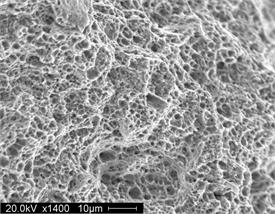
(1) SEM view of dimpled fracture resulting from tensile overload of a ductile material.
High magnification examination of a fracture surface is critical to the metallurgist during the course of a failure investigation. Close examination of the topography and fracture features can help to determine the fracture mode as well as determine the fracture origin and crack direction. The Scanning Electron Microscope is very important in the proper evaluation and classification of a fracture surface. The greater depth of field provided by the SEM allows high resolution imagery of rough surfaces at higher magnifications. Some typical fracture features revealed by Scanning Electron Microscopy (SEM) are discussed below.
Ductile Rupture: Ductile fractures are characterized by high amounts of plastic deformation just prior to fracture compared to brittle fractures. Ductile fractures often initiate at voids, or inclusions, forming distinct elongated dimples such as shown in photo (1).

(2) SEM view of transgranular cleavage fracture caused by impact overload of a material with low ductility.
Brittle Fracture: Brittle failure of materials can occur by two distinct methods. Cleavage fractures occur across crystallographic planes creating distinct ledges or steps, often containing river patterns that allow the metallurgist to determine the direction of crack progression.
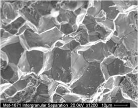
(3) SEM view of intergranular fracture that occurred in a hardened, brittle steel with microstructural precipitates that weakened the grain boundaries.
Intergranular fracture, sometimes referred to as “Rock Candy fractures” are low energy failures that occur along the grain boundaries due to processing problems or the influence of phases or substances that weaken the grain boundaries, making them susceptible to crack propagation during loading.
Typical examples of these types of fracture features are shown in SEM micrographs (2) and (3).
Fatigue Fracture: Fatigue fractures occur at stress levels below the yield strength of the material and are a common and serious problem with many material applications. Cracks can initiate at grain boundary dislocations, inclusions, pits, surface or near surface flaws, and at geometric stress raisers. Fatigue cracks can be started by or assisted by outside contaminants that cause corrosion or generate compounds that further increase stresses at the crack tip.
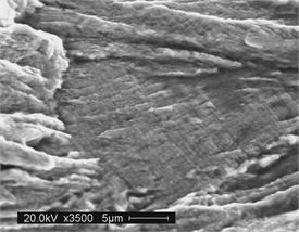
(4) SEM view of uniform striations that can sometimes be seen in fatigue cracking. In this case each striation represents a single load cycle experienced in service.
Once cracks have initiated they propagate through slow, progressive cyclic advancement, that corresponds to the repeated load applications that can occur under thousands or even millions of cycles. A classic example of striations that can result from fatigue crack progression is shown in photo (4).